INSTALLATION / GEOMETRY / REPLACEMENT
Ultrasonic level sensor blocking distance & installation guide
Allow the dead zone, keep the echo path clear and compare more than the process thread before replacing an existing transmitter.
Reviewed by UltrasonicLevelSensors technical content team · 2026-11-18
INSTALLATION WORKSHEET
Check the space your echo needs.
Empty distance is measured from the acoustic face to the zero-level datum. Full beam angle is the included angle, not the half angle.
Acoustic face → liquid
- Clearance beyond blocking distance
- 4.430 m
- Beam width at liquid surface
- 0.655 m
Exceeds your entered blocking distance and margin. This is a geometry check, not installation approval.
Geometric screening only. Use the selected sensor manual for beam definition, blanking, nozzle limits and safety margin. The additional margin is your project assumption, not a universal recommended allowance. Current-output scaling is separate from face-to-zero distance.Three installation checks that matter
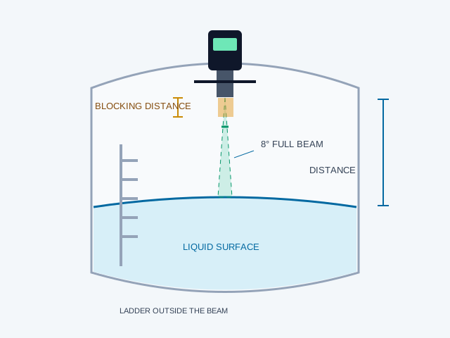
- Clear the highest credible liquid level. Face-to-full distance must exceed the specified blocking distance plus the application margin. A sensor cannot receive a useful near echo while its transducer is still ringing.
- Keep obstructions outside the beam. Locate away from filling jets, ladders and agitators. False-echo suppression can reject certain fixed echoes; it cannot bend the beam or guarantee a reading through an obstruction. Commission with actual operating conditions.
- Review every nozzle or stilling tube. Avoid burrs, weld beads and abrupt diameter changes. A stilling tube is model-specific and needs suitable diameter, smooth walls, venting and liquid communication. It is not the same as a short raised mounting nozzle.
Wiring: choose the actual circuit
A two-wire 4–20 mA transmitter is powered in its current loop. A four-wire transmitter has separate power and signal connections. RS485 needs correct A/B polarity, reference, termination, baud rate and register map. HART needs compatible loop conditions and a documented device implementation. Never infer terminal numbers or wire colours from a product-family illustration.
Replacement review: thread + signal is the start
| Existing equipment | Compare before proposing a ULS configuration |
|---|---|
| Siemens Milltronics / Probe LU / SITRANS LU | Exact model, thread standard, blind zone, range, face position, loop load, HART functions and approvals. |
| Pulsar dBi / dB / Ultra | Standalone transmitter versus matched transducer/controller interface. Proprietary connections need a validated paired package. |
| KEYENCE / Banner / Pepperl+Fuchs | Confirm sensing technology and exact model. Compact switching outputs and guide-pulse products are not automatically equivalent to tank transmitters. |
| Flowline EchoPod / EchoTough; Dwyer / APG / Gems / SICK / MJK | Power, signal, relay/control logic, mechanical envelope, dead zone and environmental conditions. |
| SOR ultrasonic gap switch | Gap geometry, insertion length, alloy, drainage, contact duty, fail state, delay and required approvals. |
No universal 1:1 drop-in compatibility is claimed. Third-party marks identify existing equipment only; we are independent of the named manufacturers.
Ultrasonic vs radar: when the application changes
Atmospheric water tanks, suitable chemical tanks and open channels can suit economical ultrasonic ranging. Dense steam, changing gas composition, heavy foam, high pressure or severe temperature can defeat through-air acoustic measurement; radar or another technology may then be more suitable after review. Deep-well hydrostatic measurement can be practical where the acoustic path is obstructed, but depth alone is not a universal 30 m technology boundary. This catalogue supplies acoustic product families only.
Questions before selection
Can temperature compensation correct every vapour?
No. Air-temperature compensation adjusts the assumed speed of sound for temperature. Gas composition, gradients and condensation can still impair measurement.
Does a PVDF probe make every acid tank suitable?
No. Check concentration, temperature, seals, housing exposure and the gas path. Material compatibility and acoustic suitability are separate reviews.
Can a gap switch ignore coating and foam?
Not universally. Bubbles, trapped liquid and deposits bridging the gap can change the detected state. Assess actual liquid, cleaning and orientation.
Can an external switch measure any LP cylinder?
No. Vessel wall, couplant, lining, temperature and installation approval need review and a representative trial. Point detection is not continuous ranging.
Technical reference sources
Reviewed 2026-11-18. These manufacturer documents support general engineering guidance. Their specifications and approvals do not transfer to ULS configurations.
- Siemens SITRANS Probe LU240 operating instructions ↗Mounting, blocking distance and obstruction troubleshooting; reference manufacturer only.
- Flowline ultrasonic level measurement ↗General application screening; not a ULS specification.
- Pulsar Measurement installation FAQ ↗Blanking distance, transducer/controller interfaces and installation.
- SOR 2700 ultrasonic level switch catalogue ↗Gap-switch liquid, drainage and bubble limitations; not ULS approvals.
- KEYENCE level-sensor technology overview ↗Check sensing principle before replacement: FL guide-pulse and FW ultrasonic are different technologies.
START WITH YOUR PROCESS
A useful quotation starts with the tank.
Send the medium, dimensions, connection and signal. Replacing an existing device? Include its exact model and controller.